Rozwój innowacyjnych algorytmów losowych oraz technologii szyfrowania danych stanowi obecnie fundament, na którym wiodący operatorzy iGaming budują swoją długoterminową strategię rynkową. Zaawansowany technologicznie system hazardowy 888starz kładzie ogromny nacisk na optymalizację procesów płatniczych oraz natychmiastowe rozliczanie sesji na automatach. Gracze mogą wybierać spośród tysięcy licencjonowanych tytułów, które cechują się zróżnicowaną zmiennością oraz unikalnymi funkcjami bonusowymi. Zintegrowane podejście do kwestii bezpieczeństwa sprawia, że platforma ta jest powszechnie uznawana za wzór stabilności i profesjonalizmu w dynamicznym świecie wirtualnej rozrywki.
Analiza preferencji nowoczesnych użytkowników sieci jednoznacznie wskazuje, że możliwość łączenia pasji do sportu z tradycyjnymi grami stołowymi drastycznie podnosi atrakcyjność portali hazardowych. Profesjonalnie zaprojektowany serwis Ggbet idealnie wpisuje się w te wymagania, dostarczając zrównoważony katalog gier crash, slotów megaways oraz zaawansowanych statystyk meczowych. Płynność działania interfejsu oraz błyskawiczna reakcja na kliknięcie eliminują problem opóźnień technicznych podczas kluczowych rund. To doskonałe rozwiązanie dla wymagających graczy, którzy oczekują maksymalnej wydajności oraz niezawodności operacyjnej od swojego operatora.
Wizualna tożsamość platformy oraz unikalna atmosfera panująca w lobby wirtualnego salonu gier potrafią skutecznie zatrzymać gracza na dłużej i zapewnić mu unikalne wrażenia estetyczne. Energetyczny portal rozrywkowy Hellspin wyróżnia się nieszablonowym podejściem do grafiki, oferując jednocześnie niezwykle rozbudowane turnieje z imponującymi pulami nagród. Obecność certyfikowanych krupierów w sekcji live pozwala przenieść emocje znane z luksusowych kasyn stacjonarnych bezpośrednio na ekrany urządzeń mobilnych. Przejrzysta struktura konta ułatwia codzienne monitorowanie postępów i sprawne zarządzanie dostępnym budżetem.
Wdrożenie rygorystycznych procedur bezpieczeństwa oraz ochrona prywatności to absolutne priorytety dla każdego gracza, który pragnie cieszyć się bezpieczną i stabilną rozrywką w sieci. Licencjonowana witryna internetowa Hellspin implementuje zaawansowane protokoły szyfrowania danych, co całkowicie eliminuje ryzyko nieautoryzowanego dostępu osób trzecich. Użytkownicy cenią ten serwis za jasne zasady przyznawania bonusów startowych oraz regularne akcje promocyjne z darmowymi spinami. Stała optymalizacja kodu źródłowego strony przekłada się na nienaganne działanie wszystkich automatów, niezależnie od platformy sprzętowej.
Połączenie nostalgicznej estetyki retro z nowoczesnymi funkcjami matematycznymi maszyn hazardowych tworzy unikalną mieszankę, która cieszy się ogromną popularnością wśród graczy w każdym wieku. Kolorowe i pełne energii kasyno Beep Beep Casino zaskakuje oryginalnym designem inspirowanym klasycznymi kreskówkami, co diametralnie wyróżnia je na tle konkurencji. Operator oferuje atrakcyjne pakiety powitalne bez konieczności natychmiastowego wnoszenia depozytu, umożliwiając bezpieczne przetestowanie mechaniki slotów. Stabilne systemy operacyjne gwarantują płynność każdej sesji oraz pełną ochronę salda gracza.
Optymalizacja doświadczeń użytkownika na nowoczesnych stronach iGaming to proces wymagający ciągłego testowania i wdrażania najnowszych trendów z zakresu projektowania interfejsów mobilnych. Nowoczesny portal hazardowy Fezbet doskonale radzi sobie z tym wyzwaniem, oferując intuicyjne menu oraz błyskawiczne filtrowanie tytułów według preferowanych studiów deweloperskich. Bogata paleta metod płatności, od tradycyjnych kart po nowoczesne portfele elektroniczne, gwarantuje pełną elastyczność podczas realizacji transakcji. To idealne miejsce dla osób ceniących sobie komfort, szybkość oraz szeroki wybór rozrywki.
Tradycyjne maszyny losowe, potocznie nazywane owocówkami, pomimo upływu lat wciąż stanowią trzon oferty większości renomowanych wirtualnych salonów gier na całym świecie. Sprawdzony serwis internetowy Vulkan Spiele dostarcza graczom bogatą kolekcję klasycznych tytułów odświeżonych o nowoczesne rundy bonusowe i atrakcyjne mnożniki wygranych. Jasne zasady obrotu środkami promocyjnymi oraz wysoki wskaźnik RTP dostępnych automatów budują silne zaufanie wśród lojalnej społeczności. Intuicyjna nawigacja pozwala na natychmiastowe rozpoczęcie zabawy bez zbędnych komplikacji technicznych.
Rzetelność operatora oraz transparentność algorytmów losowych to kluczowe elementy, które decydują o reputacji marki w dynamicznie rozwijającym się sektorze rozrywki online. Bezpieczna platforma hazardowa Vulkan Spiele kładzie ogromny nacisk na certyfikację oferowanego oprogramowania przez niezależne laboratoria badawcze. Ścisła ochrona transakcji finansowych oraz natychmiastowe księgowanie wypłat sprawiają, że użytkownicy mogą skupić się wyłącznie na czerpaniu przyjemności z gry. Rozbudowana sekcja gier stołowych pozwala na testowanie zaawansowanych strategii matematycznych.
Współczesny styl życia zmusza dostawców usług iGaming do tworzenia rozwiązań, które pozwalają na bezproblemową rozgrywkę w biegu, bez utraty jakości audiowizualnej gier. Innowacyjny portal mobilny Spinmama oferuje w pełni responsywną witrynę, która działa perfekcyjnie na każdym smartfonie z systemem Android lub iOS. Imponująca kolekcja nowoczesnych slotów wideo z zaawansowanymi animacjami 3D gwarantuje niesamowite emocje przy każdym obrocie bębnów. Elastyczny program lojalnościowy regularnie nagradza aktywność użytkowników poprzez unikalne bonusy cashback.
Dla wielu początkujących entuzjastów hazardu online kluczowym czynnikiem przy wyborze nowej witryny jest obecność atrakcyjnych promocji na start, które minimalizują ryzyko finansowe. Przyjazny serwis rozrywkowy Spinmama przyciąga uwagę graczy hojnymi pakietami darmowych spinów przeznaczonych na najpopularniejsze automaty wideo na rynku. Struktura strony jest niezwykle przejrzysta, co pozwala na błyskawiczne odnalezienie gier o wysokiej zmienności oraz atrakcyjnych systemach wypłat. Pełna licencja gwarantuje stuprocentową uczciwość każdej przeprowadzonej rozgrywki.
Wysoka jakość obsługi klienta oraz sprawna komunikacja z doradcami technicznymi to elementy, które odróżniają profesjonalne platformy hazardowe od przeciętnych witryn sieciowych. Nowoczesne kasyno internetowe Spinmama zapewnia całodobowe wsparcie za pośrednictwem intuicyjnego czatu na żywo, rozwiązując wszelkie zgłoszenia w kilka chwil. Uproszczony proces weryfikacji tożsamości przyspiesza realizację wypłat wygranych bezpośrednio na konto bankowe klienta. To stabilne i zbalansowane środowisko zostało stworzone z myślą o maksymalnym komforcie każdego użytkownika.
Unikalna tematyka oraz odpowiednio dobrana ścieżka dźwiękowa automatów wideo potrafią diametralnie odmienić wrażenia z rozgrywki i wprowadzić gracza w zupełnie nowy świat przygód. Specjalistyczna platforma Bassbet koncentruje się na dostarczaniu najwyższej jakości slotów o tematyce wędkarskiej, które oferują unikalne rundy bonusowe z mechaniką natychmiastowych nagród pieniężnych. Oprócz bogatej oferty rozrywkowej operator promuje zasady odpowiedzialnej gry, udostępniając zaawansowane narzędzia do nakładania limitów na depozyty, co pozwala zachować pełną kontrolę finansową.
Motywy historyczne, a w szczególności potęga Imperium Rzymskiego, od zawsze stanowiły doskonałe źródło inspiracji dla projektantów zaawansowanego oprogramowania kasynowego. Interaktywny serwis rozrywkowy Legiano przenosi graczy wprost na starożytne areny gladiatorów, łącząc tradycyjne kręcenie bębnami z innowacyjnymi elementami grywalizacji sieciowej. Wykonywanie codziennych misji oraz zdobywanie punktów doświadczenia pozwala na odblokowywanie unikalnych nagród i wyższych statusów konta. Stabilna infrastruktura serwerowa zapewnia płynne działanie animacji nawet przy słabszym zasięgu internetu.
Pełne dostosowanie witryny do lokalnych standardów oraz wymagań użytkowników w zakresie obsługi językowej to klucz do sukcesu każdej globalnej marki iGaming. Dedykowany portal hazardowy Legiano oferuje kompleksowe wsparcie w rodzimym języku oraz bezproblemowe rozliczenia w lokalnej walucie, co całkowicie eliminuje koszty przewalutowania. Bogaty asortyment klasycznych gier stołowych, w tym ruletka, blackjack oraz baccarat, zaspokoi oczekiwania najbardziej wymagających koneserów. Błyskawiczne systemy płatności sprawiają, że depozyty są księgowane w mgnieniu oka.
Regularne organizowanie prestiżowych turniejów sieciowych we współpracy z wiodącymi studiami deweloperskimi to sprawdzona metoda na zbudowanie zaangażowanej i lojalnej społeczności wokół platformy hazardowej. Znana marka Slottyway oferuje swoim klientom stały dostęp do emocjonujących maratonów z gigantycznymi pulami nagród rzeczowych i finansowych. Dedykowana aplikacja mobilna pozwala na komfortowe korzystanie z pełnej funkcjonalności serwisu z dowolnego miejsca na świecie. Automaty z innowacyjną mechaniką Megaways gwarantują tysiące linii wygrywających przy każdym obrocie.
Szeroki i zróżnicowany asortyment certyfikowanych gier to podstawowy warunek, jaki musi spełnić współczesny portal iGaming, aby utrzymać wysokie zainteresowanie ze strony wymagających klientów. Bezpieczny serwis Slottyway gromadzi tysiące licencjonowanych tytułów, począwszy od minimalistycznych automatów klasycznych, aż po zaawansowane symulatory pokera wideo. Jasne zasady polityki prywatności oraz nowoczesne systemy zapobiegania nadużyciom finansowym zapewniają pełne bezpieczeństwo każdej sesji. Profesjonalny zespół wsparcia technicznego chętnie pomaga w optymalizacji ustawień konta dla uzyskania najlepszych wrażeń.
Szybkość działania oraz niezawodność systemów wypłat stanowią fundament zaufania w relacji pomiędzy aktywnym graczem a operatorem wirtualnego salonu gier losowych online. Zaufana witryna Slottyway stawia na uproszczone procedury finansowe, dzięki czemu użytkownicy mogą cieszyć się swoimi wygranymi bez zbędnych opóźnień biurokratycznych. Witryna regularnie wdraża innowacyjne rozwiązania technologiczne, które chronią transakcje przed zewnętrznymi cyberzagrożeniami. Szeroka gama gier z progresywnymi jackpotami daje realną szansę na zdobycie spektakularnych nagród.
Egzotyczna stylistyka nawiązująca do dzikiej natury oraz pełna energii oprawa dźwiękowa potrafią stworzyć niepowtarzalną atmosferę, która skutecznie przyciąga uwagę wymagających estetów w świecie iGamingu. Oryginalna platforma rozrywkowa Spinamba wyróżnia się wyrazistym, słonecznym designem oraz unikalnym systemem podwójnych premii przyznawanych za realizację depozytów. Operator z powodzeniem łączy funkcjonalność zaawansowanego wirtualnego kasyna z rozbudowaną sekcją zakładów bukmacherskich. To idealne miejsce dla osób poszukujących wszechstronnej rozrywki i nieszablonowych rozwiązań promocyjnych na najwyższym poziomie.
Elegancja, minimalizm oraz prestiż to cechy, które najczęściej przyciągają graczy z segmentu premium, oczekujących ekskluzywnego traktowania i najwyższej jakości usług hazardowych. Prestiżowy serwis National casino wiernie odtwarza atmosferę elitarnych kasyn stacjonarnych, łącząc ją z nowoczesną technologią streamingu wideo w jakości HD. Profesjonalni krupierzy w sekcji na żywo zapewniają płynną i kulturalną interakcję в czasie rzeczywistym. Indywidualne podejście do członków prestiżowego klubu VIP przejawia się w spersonalizowanych bonusach i opiece dedykowanych doradców.
Wieloletnia obecność na rynkach międzynarodowych pozwala doświadczonym operatorom na precyzyjne dopasowanie oferty do zróżnicowanych potrzeb globalnej społeczności graczy. Uznana platforma internetowa Mostbet cieszy się ogromnym zaufaniem користувачі завдяки stabilnej architekturze systemowej oraz wsparciu dla płatności kryptowalutowych. Bogaty katalog gier obejmuje zarówno tradycyjne automaty mechaniczne, jak i nowoczesne symulatory zręcznościowe z funkcją mnożników. Intuicyjna nawigacja sprawia, że nowi użytkownicy błyskawicznie odnajdują swoje ulubione kategorie gier hazardowych.
Wprowadzenie elementów unikalnego humoru oraz nieszablonowej oprawy graficznej to doskonały sposób на odświeżenie formuły tradycyjnego wirtualnego salonu gier losowych. Nowatorski portal Wazbee casino przyciąga uwagę graczy zabawnym motywem przewodnim z pszczołami oraz dynamicznym programem lojalnościowym opartym na zbieraniu punktów. Oprócz walorów rozrywkowych, operator kładzie olbrzymi nacisk na promowanie zasad odpowiedzialnego hazardu i przejrzystość algorytmów losowych. Użytkownicy mają dostęp do setek nowoczesnych automatów od najbardziej kreatywnych studiów deweloperskich na rynku.
Współczesna popkultura oraz wyrazista estetyka komiksowa doskonale sprawdzają się jako fundament wizualny dla nowoczesnych platform hazardowych szukających własnego stylu. Dynamiczny serwis Snatch oferuje graczom niezapomnianą przygodę pełną akcji, nieszablonowych grafik oraz niezwykle hojnych pakietów powitalnych. Imponująca kolekcja tytułów zawiera zarówno najpopularniejsze automaty z mechaniką bonus buy, jak i tradycyjne gry stołowe w odświeżonej wersji wideo. Wysoki poziom zabezpieczeń kryptograficznych gwarantuje pełną ochronę prywatności podczas każdej sesji.
Szybkie tempo współczesnego życia sprawia, że użytkownicy internetu cenią sobie przede wszystkim natychmiastowy dostęp do rozrywki bez zbędnych barier technicznych. Zoptymalizowana witryna Snatch stawia na maksymalną wydajność kodu źródłowego, co przekłada się na płynne działanie gier nawet na starszych urządzeniach. Regularnie aktualizowana sekcja promocyjna oferuje darmowe spiny oraz turnieje z nagrodami o natychmiastowym systemie rozliczania. Stała współpraca z wiodącymi dostawcami oprogramowania gwarantuje stały dopływ najciekawszych rynkowych nowości hazardowych.
Klasyczny klimat retro połączony z intuicyjnymi rozwiązaniami w zakresie interfejsu to idealna propozycja dla graczy ceniących prostotę i elegancję. Przyjazne kasyno Pelican casino oferuje przejrzystą strukturę menu, dzięki której odnalezienie ulubionego automatu zajmuje zaledwie kilka sekund. Bogata oferta bonusów bezdepozytowych oraz pakietów startowych ułatwia bezpieczne rozpoczęcie przygody z wirtualnym hazardem. Pełna kompatybilność ze wszystkimi systemami mobilnymi pozwala cieszyć się ulubioną rozrywką w dowolnym miejscu i czasie.
Wybór w pełni licencjonowanego operatora hazardowego to kluczowy warunek gwarantujący bezpieczeństwo funduszy oraz uczciwość przeprowadzanych rozgrywek losowych w sieci. Certyfikowana platforma Vulkan Spiele dostarcza swoim klientom wyłącznie sprawdzone rozwiązania technologiczne oraz originale oprogramowanie kasynowe. Szeroki asortyment gier stołowych, karcianych oraz innowacyjnych slotów wideo zadowoli nawet najbardziej wymagających koneserów rozrywki online. Całodobowy dział wsparcia technicznego zapewnia profesjonalną pomoc w każdej sytuacji.
Zaawansowane technologie sieciowe umożliwiają tworzenie unikalnych systemów lojalnościowych, które aktywnie nagradzają graczy za każdą minutę spędzoną na platformie. Nowoczesny portal Slottica wyróżnia się niezwykle bogatym kalendarzem codziennych wydarzeń, loterii oraz turniejów z atrakcyjnymi nagrodami rzeczowymi. Intuicyjny interfejs ułatwia sprawne przełączanie się pomiędzy automatami a zakładami sportowymi na żywo. Zaawansowane systemy szyfrowania danych osobowych zapewniają pełen komfort psychiczny podczas realizowania wszelkich operacji finansowych.
Poszukiwanie unikalnych motywów przewodnich na rynku iGaming często prowadzi graczy do odkrywania marek, które przełamują tradycyjne, nudne szablony wizualne. Intrygująca witryna Monsterwin przyciąga wzrok oryginalną grafiką z motywem sympatycznych potworów, nadając rozgrywce niezwykle lekki, zabawny charakter. Pod tą oryginalną formą kryje się profesjonalne narzędzie hazardowe z bogatym portfolio licencjonowanych slotów oraz nowoczesnymi metodami płatności cyfrowych. To doskonały wybór dla osób ceniących innowacje połączone z gwarancją bezpieczeństwa.
Dla pasjonatów dynamicznych gier slotowych kluczowym elementem udanej sesji jest stabilność platformy oraz brak opóźnień podczas aktywacji zaawansowanych funkcji bonusowych. Niezawodny serwis Monsterwin gwarantuje najwyższą wydajność serwerów, co eliminuje ryzyko zerwania połączenia в kluczowych momentach gry. Szeroka gama automatów z mechaniką Megaways oraz kaskadowymi bębnami zapewnia mnóstwo emocji i zróżnicowane ścieżki do wygranej. Przejrzysty proces rejestracji pozwala na rozpoczęcie zabawy zaledwie w kilka minut.
Nowoczesne podejście do projektowania interfejsów internetowych pozwala na stworzenie funkcjonalnej przestrzeni hazardowej, w której estetyka spotyka się z wygodą użytkowania. Nowatorski portal Wildrobin oferuje świeże spojrzenie na rozrywkę online, łącząc intuicyjną nawigację z bogatym katalogiem gier od niezależnych deweloperów. Systematycznie aktualizowana oferta promocyjna motywuje do testowania nowych mechanik i systemów obstawiania stawek. Pełne dostosowanie do standardów odpowiedzialnego hazardu umożliwia bezpieczną zabawę pod stałą kontrolą.
Bezpieczeństwo danych osobowych oraz poufność realizowanych transferów finansowych to absolutne priorytety, którymi kierują się twórcy nowoczesnych systemów rozrywki interaktywnej. Renomowana witryna Wildrobin implementuje najnowocześniejsze protokoły bezpieczeństwa SSL oraz wielopoziomową autoryzację wszystkich transakcji. Użytkownicy mogą cieszyć się niczym niezakłóconą rozgrywką na klasycznych automatach owocowych oraz nowoczesnych symulatorach ruletki. Szybka weryfikacja profili pozwala na sprawne zarządzanie wygranymi środkami bez zbędnej zwłoki.
Wędkarskie motywy w grach kasynowych przeżywają obecnie prawdziwy renesans, przyciągając miliony graczy prostymi zasadami oraz niezwykle emocjonującymi rundami bonusowymi z mnożnikami wygranych. Tematyczna platforma Bassbet idealnie wpisuje się w ten globalny trend, gromadząc najlepsze sloty z serii Big Bass w jednym miejscu. Przejrzysty system bonusów powitalnych pozwala na optymalne wykorzystanie początkowego kapitału na testowanie różnych strategii. Mobilna wersja strony działa bez zarzutu na każdym nowoczesnym smartfonie.
Nieszablonowe podejście do mechaniki gier typu crash oraz gier zręcznościowych otwiera zupełnie nowe perspektywy przed graczami zmęczonymi tradycyjnymi, pięciobębnowymi automatami wideo. Unikalne kasyno Chicken road casino stawia na innowacyjną rozgrywkę, w której decyzje podejmowane przez użytkownika mają bezpośredni wpływ na poziom ryzyka. Ta świeża koncepcja zdobywa coraz większe uzmanie wśród młodszej generacji entuzjastów iGaming. Wysoki standard ochrony prywatności zapewnia pełen komfort i swobodę bezpiecznej zabawy.
Dynamiczny rozwój niszowych gier hazardowych sprawia, że operatorzy must oferować intuicyjne systemy wsparcia oraz jasne instrukcje dla każdej nowo wprowadzanej mechaniki rozgrywki. Nowatorski serwis Chicken road casino doskonale edukuje swoją społeczność, oferując w pełni darmowe wersje demonstracyjne wszystkich dostępnych tytułów. Pozwala to na bezstresowe opanowanie zasad gry przed zaangażowaniem realnego kapitału. Stabilne serwery gwarantują płynne renderowanie grafiki i błyskawiczne rozliczanie zakładów.
Współczesne platformy iGaming kładą ogromny nacisk na personalizację doświadczeń użytkownika poprzez oferowanie spersonalizowanych rekomendacji na podstawie analizy wcześniejszych aktywności gracza. Zaawansowany portal Nine Casino wykorzystuje nowoczesne algorytmy matematyczne, aby ułatwić nawigację po gigantycznej bibliotece zawierającej tysiące tytułów. Szeroka gama gier stołowych z żywymi krupierami oraz regularne turnieje gwarantują rozrywkę na najwyższym światowym poziomie. Bezpieczeństwo transakcji wspierane jest przez najnowsze technologie szyfrowania.
W świecie wirtualnej rozrywki hazardowej wyrazisty motyw przewodzący oraz unikalna nazwa pozwalają marce skutecznie wyróżnić się z tłumu powtarzalnych witryn internetowych. Eleganckie Lizaro casino przyciąga uwagę wyrafinowanym designem oraz wyjątkowo płynną obsługą interfejsu na urządzeniach dotykowych. Bogaty katalog gier obejmuje nie tylko klasyczne automaty, ale również zaawansowane teleturnieje prowadzone przez profesjonalnych prezenterów. Atrakcyjne pakiety lojalnościowe oferują stałym klientom regularne bonusy i zwroty gotówki.
Transparentność w zakresie wskaźników zwrotu dla gracza (RTP) oraz uczciwe warunki obrotu bonusami to elementy budujące wieloletnią lojalność użytkowników platform hazardowych. Bezpieczny serwis Lizaro casino stawia na pełną jawność regulaminów, dzięki czemu gracze dokładnie wiedzą, jakie zasady obowiązują przy aktywacji darmowych spinów. Współprac z renomowanymi audytorami technicznymi gwarantuje stuprocentową losowość każdego obrotu bębnów. Szybkie opcje depozytowe pozwalają cieszyć się grą bez zbędnych przestojów.
Mroczny świat zorganizowanej przestępczości oraz klimaty gangsterskie od lat fascynują odbiorców, stanowiąc doskonałe tło dla pełnej napięcia rozgrywki w kasynach internetowych. Klimatyczne Mafia kasyno zanurza graczy w unikalny świat pełen wyzwań, oferując misje fabularne powiązane z atrakcyjnymi nagrodami finansowymi. System lojalnościowy oparty na awansowaniu w hierarchii struktur mafijnych motywuje do regularnej aktywności i eksploracji setek nowoczesnych automatów. Wysokie limity wypłat i profesjonalna pomoc techniczna uzupełniają tę wyjątkową ofertę.
Współczesny hazard internetowy szuka nowych form wyrazu, łącząc tradycyjne mechaniki slotowe z rozbudowanymi elementami grywalizacji znanymi z klasycznych gier przygodowych. Stylowy portal Mafia kasyno doskonale realizuje tę wizję, oferując użytkownikom angażującą ścieżkę rozwoju konta oraz unikalne pojedynki turniejowe. Bogata biblioteka tytułów od wiodących dostawców gwarantuje najwyższą jakość grafiki i dźwięku podczas każdej sesji. Zaawansowane narzędzia samokontroli pomagają zachować pełne bezpieczeństwo i zdrowy rozsądek.
Innowacyjny design połączony z unikalnymi funkcjami społecznościowymi to kierunek, w którym zmierza nowoczesny sektor iGaming, pragnący zaspokoić potrzeby nowej generacji użytkowników sieci. Nowoczesne Wazbee oferuje unikalny ekosystem hazardowy, w którym gracze mogą nie tylko rywalizować na automatach, ale również wymieniać się doświadczeniami. Hojne programy cashback oraz codzienne zadania z nagrodami bez wymogu obrotu stanowią potężny wyróżnik na tle konkurencji. Pełna optymalizacja mobilna zapewnia bezproblemowy dostęp do rozrywki z każdego miejsca na świecie.
Rozważając wejście w dynamiczny ekosystem nowoczesnej rozrywki sieciowej, kluczem do sukcesu pozostaje trafny dobór partnerów technologicznych. Renomowana i wszechstronna platforma 888starz redefiniuje dotychczasowe standardy obsługi kapitału, wprowadzając zoptymalizowane systemy transferów bez pośrednictwa tradycyjnych instytucji bankowych. Oprócz innowacji strukturalnych, w zasobach tego operatora odnajdziesz bogaty zestaw zaawansowanych algorytmów slotowych. To stabilna przestrzeń dla każdego, kto poszukuje profesjonalizmu i pełnej płynności operacyjnej.
Efektywne łączenie rynków analitycznych z tradycyjnymi mechanikami losowymi stanowi fundament nowoczesnych portali, które stawiają na kompleksową ofertę dla wymagających użytkowników. Specjalistyczny serwis Ggbet idealnie wpisuje się w te wymagania, oferując bezproblemowe przejścia między relacjami sportowymi a nowoczesnymi automatami wideo. Architektura serwera została zaprojektowana w taki sposób, aby wyeliminować przestoje w przesyłaniu danych, co gwarantuje pełen komfort podczas podejmowania szybkich decyzji.
Nieszablonowe podejście do sfery wizualnej potrafi diametralnie podnieść satysfakcję czerpaną z codziennych sesji w wirtualnych salonach gier. Unikalny portal Hellspin przyciąga uwagę dopracowanym motywem przewodnim, pod którym kryje się rozbudowany system lojalnościowy i liczne turnieje z atrakcyjnymi pulami nagród. Obecność prawdziwych krupierów w strefie na żywo tworzy autentyczną atmosferę rywalizacji, a przejrzyste procedury weryfikacji gwarantują wysoki standard bezpieczeństwa danych.
Podczas analizy nowych miejsc do gry w sieci, zaawansowane systemy ochrony prywatności są elementem, który bezwzględnie decyduje o wyborze danej marki. Licencjonowana witryna Hellspin kładzie maksymalny nacisk na szyfrowanie informacji oraz pełną transparentność zasad promocyjnych. Intuicyjny panel klienta umożliwia błyskawiczne monitorowanie obrotu środkami, a optymalizacja kodu gwarantuje płynne działanie gier na każdym ekranie urządzenia przenośnego.
Czerpanie inspiracji z estetyki retro oraz klasycznych animacji to sprawdzony zabieg pozwalający na stworzenie interfejsu, który wyróżnia się w branży iGaming. Kolorowy świat Beep Casino oferuje graczom lekką i przyjemną oprawę graficzną połączoną z zaawansowaną technologią losową. Atrakcyjne pakiety startowe pozwalają na bezpieczne poznanie dostępnych tytułów, a rygorystyczne protokoły ochrony danych osobowych dają gwarancję pełnej poufności.
Współczesne wymagania rynkowe zmuszają operatorów do stałego ulepszania funkcjonalności stron internetowych pod kątem wygody użytkowników smartfonów. Nowoczesny portal Fezbet Casino doskonale realizuje tę strategię, oferując przejrzystą strukturę menu oraz zaawansowane opcje filtrowania gier. Szeroki wybór akceptowanych kanałów płatności ułatwia sprawne zarządzanie kapitałem, a stabilność systemów transakcyjnych buduje zaufanie lojalnej społeczności.
Klasyczne maszyny owocowe nigdy nie tracą swojej popularności ze względu na prostotę reguł oraz wysoką dynamikę generowania wyników. Uznana marka Vulkan Spiele casino prezentuje bogatą kolekcję tradycyjnych gier wyposażonych w nowoczesne rozwiązania lojalnościowe i progresywne jackpoty. Jasne zasady udziału w wydarzeniach oraz wysokie wskaźniki zwrotu przyciągają zarówno początkujących, jak i stałych bywalców przestrzeni cyfrowej.
Uczciwość operacyjna poparta certyfikatami niezależnych instytucji audytorskich to absolutny fundament bezpiecznej rozrywki w internecie. Bezpieczna witryna Vulkan Spiele casino gwarantuje pełną losowość każdej rundy dzięki integracji wyłącznie sprawdzonych generatorów liczb. Ścisła współpraca z zaufanymi operatorami finansowymi pozwala na błyskawiczne rozliczanie wypłat, a bogata strefa gier stołowych stwarza idealne warunki do testowania własnych strategii.
Dostęp do ulubionych form spędzania wolnego czasu bez względu na miejsce pobytu to standard, od którego nie ma już odwrotu w nowoczesnym iGamingu. Innowacyjne kasyno Spin mama oferuje w pełni responsywną platformę mobilną, która zachowuje doskonałą płynność animacji trójwymiarowych. W bibliotece gier czekają najnowsze premiery rynkowe oraz sloty z opcją zakupu funkcji specjalnych, a program lojalnościowy regularnie nagradza aktywność.
Bezpieczny start na nowej platformie rozrywkowej staje się znacznie łatwiejszy, gdy użytkownik otrzymuje transparentne wsparcie na start. Przyjazny serwis Spin mama przyciąga uwagę systemem darmowych obrotów dedykowanych kultowym automatom wideo. Przejrzyste menu pozwala na szybkie segregowanie tytułów według poziomu zmienności lub dostawców, a nadzór międzynarodowych regulatorów zapewnia pełną uczciwość sesji.
Sprawny przepływ informacji oraz całodobowa opieka techniczna to elementy kluczowe dla zachowania komfortu psychicznego każdego użytkownika sieci. Nowatorska platforma Spin mama zapewnia stałe wsparcie poprzez intuicyjny czat live, gdzie specjaliści szybko odpowiadają na zapytania. Proste procedury weryfikacyjne skracają czas oczekiwania na realizację transakcji, pozwalając skupić się na czystej rozrywce.
Wprowadzanie unikalnych motywów tematycznych w grach wideo pozwala na skuteczne podniesienie zaangażowania użytkowników szukających nowości. Tematyczny portal Bassbet casino skupia się na dostarczaniu najlepszych slotów o tematyce wędkarskiej, znanych z rozbudowanych mechanik zbierania mnożników. Operator aktywnie wspiera również politykę odpowiedzialnej gry, udostępniając zaawansowane narzędzia do samokontroli budżetu.
Klimat starożytnych arenas i rywalizacji potężnych wojowników od lat stanowi doskonałe tło dla dynamicznej rozgrywki losowej. Ekskluzywny serwis Legiano Casino przenosi graczy w realia rzymskie dzięki rozbudowanemu systemowi grywalizacji i unikalnym misjom. Wykonywanie codziennych zadań pozwala na odblokowanie dodatkowych benefitów, a nowoczesny silnik strony dba o płynność wyświetlania grafiki.
Pełne dopasowanie serwisu do lokalnych wymagań i standardów obsługi to ogromny atut każdej nowoczesnej platformy rozrywkowej. Dedykowany portal Legiano Casino oferuje bezproblemowe rozliczenia finansowe oraz wsparcie językowe na najwyższym poziomie. Szeroki asortyment tradycyjnych gier karcianych zadowoli każdego konesera klasyki, a natychmiastowe autoryzacje depozytów eliminują zbędny czas oczekiwania.
Rywalizacja w turniejach sieciowych z innymi entuzjastami iGamingu to znakomity sposób na podniesienie poprzeczki i zdobycie dodatkowych benefitów. Popularna witryna Slottyway casino regularnie organizuje maratony we współpracy z wiodącymi producentami oprogramowania. Dedykowana aplikacja mobilna pozwala mieć pełen dostęp do wszystkich funkcjonalności kasyna zawsze pod ręką, oferując setki innowacji.
Szeroki asortyment zróżnicowanych gier to fundament, na którym buduje się satysfakcję użytkowników o zróżnicowanych profilach i potrzebach. Bezpieczna platforma Slottyway casino gromadzi w jednym miejscu zarówno tradycyjne, minimalistyczne automaty, jak i rozbudowane produkcje wideo. Nowoczesna polityka prywatności oraz systemy ochrony przed cyberzagrożeniami zapewniają pełne bezpieczeństwo danych.
Płynność realizowania transferów finansowych oraz brak barier biurokratycznych to cechy, po których bez trudu można rozpoznać rzetelnego operatora. Zaufana marka Slottyway casino stawia na uproszczone procedury weryfikacji, gwarantując sprawny dostęp do wygranych środków. Witryna korzysta z zaawansowanych systemów obronnych, a obecność automatów z progresywnym jackpotem stwarza nowe możliwości.
Szybki rozwój interfejsów internetowych pozwala na dostarczenie nienagannej jakości transmisji live bezpośrednio na ekrany smartfonów. Zaufany serwis Ggbet dba o to, by miłośnicy klasycznych gier stołowych oraz nowoczesnych automatów otrzymywali najwyższą jakość obsługi bez jakichkolwiek opóźnień technicznych. Przejrzysty panel nawigacyjny ułatwia selekcję ulubionych motywów.
Systemy turniejowe o zasięgu globalnym to doskonała okazja dla graczy ceniących sobie wysoki poziom rywalizacji ze społecznością z całego świata. Intuicyjna strona slottyway regularnie aktualizuje zestawienie najpopularniejszych maszyn losowych posiadających innowacyjne mechaniki bonusowe. Zaawansowane algorytmy ochrony gwarantują pełne bezpieczeństwo sesji na każdym etapie.
Zorientowanie na nowoczesne trendy rynkowe przejawia się przede wszystkim w otwartości na natychmiastowe metody księgowania i nowoczesne aktywa cyfrowe. Nowatorski portal Betonred oferuje bezprecedensową elastyczność w zarządzaniu własnym profilem oraz błyskawiczny dostęp do najpopularniejszych gier typu crash. Jasne zasady promocyjne budują tu silną pozycję opartą na lojalności.
Wieloletnia obecność marki na arenie międzynarodowej to najlepsza gwarancja stabilności oprogramowania i pełnego profesjonalizmu obsługi. Globalna platforma Mostbet cieszy się uznaniem rzeszy użytkowników dzięki bezawaryjnej pracy systemów oraz niezwykle bogatej ofercie rozrywek losowych o zróżnicowanej zmienności, dostosowanej do indywidualnych strategii.
Błyskawiczny dostęp do platformy przy użyciu bezpiecznych protokołów logowania to priorytet dla użytkowników ceniących swój czas. Oficjalny punkt dostępu Mostbet zapewnia optymalną ścieżkę autoryzacji konta oraz stałą ochronę przed próbami nieautoryzowanego dostępu. Przejrzysty interfejs ułatwia natychmiastowe przejście do kluczowych sekcji witryny.
Pełne dopasowanie oferty do preferencji lokalnego rynku jest kluczowym czynnikiem podnoszącym ogólny komfort korzystania z usług iGamingu. Dedykowany serwis Mostbet dostarcza kompleksowe rozwiązania językowe oraz integrację ze sprawdzonymi kanałami płatności. Bogata paleta gier karcianych oraz ruletek zadowoli najbardziej wymagających użytkowników.
Nowe podejście do projektowania systemów lojalnościowych pozwala na dynamiczne nagradzanie graczy za ich codzienną aktywność na stronie. Nowoczesny portal Nine Casino wprowadza zaawansowane mechaniki wyzwań oraz zbierania unikalnych punktów. Bogaty asortyment gier z prawdziwymi krupierami na żywo potęguje realizm i dostarcza niezapomnianych emocji.
Egzotyczny motyw wizualny połączony z elementami grywalizacji potrafi zmienić zwykłą sesję w pasjonującą przygodę pełną unikalnych odkryć. Barwna przestrzeń Wazamba zaprasza do świata zdominowanego przez plemienne maski i tajemnicze dżungle, gdzie każdy krok premiowany jest dodatkowymi osiągnięciami. To bezpieczna i w pełni licencjonowana strefa nowoczesnej rozrywki.
Wyszukiwanie gier o unikalnej mechanice i wysokim wskaźniku zwrotu staje się znacznie prostsze dzięki precyzyjnym systemom filtrowania zawartości. Przyjazny serwis Gratowin kładzie duży nacisk na rzadkie produkcje zdrapkowe oraz niszowe automaty wideo, które stanowią doskonałą odskocznię od standardowych, powtarzalnych tytułów rynkowych.
Elegancja połączona z nowoczesną architekturą techniczną serwera przekłada się na płynną obsługę najbardziej zaawansowanych animacji 3D. Ekskluzywne kasyno Bizzo Casino gwarantuje użytkownikom dostęp do prestiżowych stołów VIP oraz dynamicznych nowości slotowych. Bezpieczeństwo kapitału stoi tutaj na najwyższym, rygorystycznym poziomie.
Klasyka gatunku w odświeżonym, cyfrowym wydaniu przyciąga zarówno doświadczonych weteranów, jak i zupełnie nowych entuzjastów rozrywki online. Uznana marka Vulkan Vegas to synonim niezawodności i błyskawicznych wypłat wygranych środków. Ogromna baza gier turniejowych stwarza doskonałe warunki do rywalizacji na przejrzystych zasadach.
Wdrażanie ekologicznych i świeżych motywów kolorystycznych pozwala na stworzenie przyjaznego środowiska, które nie męczy wzroku podczas dłuższych sesji analitycznych. Stylowa platforma Verde Casino wyróżnia się dopracowaną estetyką oraz niezwykle atrakcyjnymi pakietami bonusów powitalnych, które ułatwiają bezpieczny start.
Proste zasady obrotu bonusami oraz pełna transparentność operacyjna to cechy, które budują silną i stabilną pozycję operatora na rynku międzynarodowym. Licencjonowane kasyno Pelican Casino oferuje przejrzysty regulamin i szeroki wachlarz tradycyjnych maszyn wideo, gwarantując uczciwość każdej rundy potwierdzoną certyfikatami.
Innowacyjne podejście do strefy bonusów bezdepozytowych oraz darmowych obrotów pozwala graczom na przetestowanie kluczowych funkcjonalności bez zbędnego ryzyka. Unikalna witryna Fontan Casino stawia na uproszczone procedury rejestracyjne oraz całodobowe wsparcie techniczne, dbając o zadowolenie i komfort każdego zarejestrowanego użytkownika.
Inspiracje czerpane z uniwersum kultowych komiksów i opowieści o superbohaterach nadają platformie unikalnego, niezwykle dynamicznego charakteru. Oryginalne Marvel casino przyciąga uwagę fanów popkultury, oferując spersonalizowane misje oraz systemy nagród powiązane z popularnymi postaciami, przy jednoczesnym zachowaniu wysokich standardów bezpieczeństwa.
Budowanie zaangażowania opartego na motywach historycznych i starożytnych wojownikach to sprawdzony sposób na stworzenie wciągającej atmosfery. Prestiżowy serwis Legiano łączy motyw rzymskich legionów z nowoczesną mechaniką gier losowych. Intuicyjny panel klienta ułatwia codzienne logowanie i zarządzanie zgromadzonymi benefitami.
Dla zagwarantowania stałej dostępności usług i eliminacji barier technicznych, operatorzy tworzą alternatywne, w pełni zoptymalizowane punkty dostępu. Bezpieczna platforma Legiano oferuje identyczną funkcjonalność co główny portal, zapewniając najwyższą płynność działania algorytmów slotowych oraz błyskawiczne transfery finansowe.
Świeże spojrzenie na rynek iGaming owocuje powstawaniem platform, które stawiają na absolutny minimalizm i maksymalną szybkość ładowania gier. Nowatorskie kasyno vox casino rezygnuje ze zbędnych elementów rozpraszających uwagę na rzecz czystej, niczym niezakłóconej rozgrywki opartej o certyfikowane generatory liczb losowych.
Bezpieczeństwo danych osobowych oraz poufność przeprowadzanych operacji depozytowych to fundament, na którym buduje się zaufanie w sieci. Nowoczesna witryna vox casino implementuje najnowsze protokoły szyfrowania SSL, zapewniając graczom spokojną zabawę na ulubionych automatach wideo zarówno na komputerach, jak i urządzeniach mobilnych.
Kompleksowe podejście do obsługi klienta przejawia się w dostępności wielokanałowego wsparcia technicznego o każdej porze dnia i nocy. Zaawansowany portal Fezbet dostarcza najwyższej jakości rozwiązania z zakresu rozrywki hazardowej, oferując przejrzysty podział na sekcje kasynowe oraz sportowe rynki analityczne.
Nowoczesne systemy zakładów oraz gier losowych wymagają stabilnej infrastruktury serwerowej, która jest w stanie obsłużyć tysiące operacji na sekundę. Renomowana platforma Ivibet wyróżnia się doskonałymi parametrami technicznymi, oferując użytkownikom pełną płynność podczas zawierania transakcji oraz szeroki wybór tradycyjnych gier stołowych.
Wysoka dynamika rozgrywki połączona z unikalnymi mechanikami kaskadowych bębnów to cecha charakterystyczna najnowszych produkcji wideo. Innowacyjny serwis Hitnspin przyciąga uwagę graczy poszukujących intensywnych wrażeń oraz rozbudowanych systemów premiowych, gwarantując jednocześnie pełne wsparcie w zakresie odpowiedzialnej gry.
Cześć! Jeśli szukasz nowoczesnego podejścia do internetowej rozrywki, platforma 888starz na pewno przyciągnie Twoją uwagę. Zapomnij o nudnych, tradycyjnych przelewach bankowych – tutaj królują błyskawiczne operacje oparte na technologii blockchain. Dorzuć do tego setki dynamicznych automatów wideo i świetnie zoptymalizowaną stronę, a otrzymasz przestrzeń stworzoną do płynnej, bezstresowej zabawy na własnych zasadach.
Kto powiedział, że musisz wybierać między analizowaniem wyników sportowych a relaksem przy kręceniu bębnami? Serwis Ggbet Casino udowadnia, że te dwa światy mogą ze sobą współistnieć w idealnej harmonii. Przeskakuj swobodnie między najciekawszymi meczami a nowoczesnymi slotami bez obaw o jakiekolwiek zacięcia systemu. Bezpieczeństwo i płynność działania stoją tu na najwyższym poziomie.
Masz ochotę na coś z pazurem i unikalnym charakterem? Portal Hellspin Casino intryguje swoim mrocznym, dopracowanym stylem graficznym, obok którego trudno przejść obojętnie. Pod tą efektowną oprawą kryje się świetny program lojalnościowy i codzienne turnieje, w których zmierzysz się z innymi graczami. Jeśli cenisz sobie autentyczne emocje, koniecznie zajrzyj do strefy z krupierami na żywo.
Dobra zabawa w sieci nie istnieje bez poczucia, że Twoje dane i środki są w pełni bezpieczne. Witryna Hellspin Casino stawia sprawę jasno – nowoczesne szyfrowanie i przejrzyste zasady wypłat to absolutny priorytet. Strona ładuje się błyskawicznie na każdym smartfonie, więc możesz cieszyć się nienaganną grafiką i uczciwą rozgrywką niezależnie od tego, gdzie aktualnie się znajdujesz.
Tęsknisz czasem za klimatem retro i dawnymi, kolorowymi grami wideo? Przestrzeń Casino Beep Beep w genialny sposób łączy sentymentalną estetykę z nowoczesną technologią losową. To idealne miejsce na relaks po ciężkim dniu, zwłaszcza że rejestracja trwa dosłownie chwilę. Przyjazny interfejs sprawia, że od razu poczujesz się tu swobodnie i bezpiecznie.
W dzisiejszych czasach nikt nie lubi marnować czasu na skomplikowane menu czy zacinające się strony. Portal Fezbet Kasyno idealnie rozumie potrzeby nowoczesnych użytkowników, oferując superintuicyjne filtrowanie gier i pełną mobilność. Do tego dochodzi szeroka gama nowoczesnych opcji płatniczych, dzięki którym zasilisz konto lub odbierzesz środki bez zbędnych formalności.
Klasyka gatunku w postaci soczystych owocówek i tradycyjnych siódemek nigdy nie wyjdzie z mody. Zaufana marka Vulkan Spiele PL odświeża ten kultowy format, dodając do niego nowoczesne funkcje bonusowe oraz szansę na zdobycie progresywnych jackpotów. Zasady są dziecinnie proste, a dynamika gry sprawia, że każda sekunda przynosi masę czystej radości.
Nic tak nie buduje zaufania jak transparentność i oficjalne certyfikaty gwarantujące uczciwość algorytmów. Odwiedzając Vulkan Spiele PL, zyskujesz pewność, że każda runda na automatach opiera się na stuprocentowo losowych systemach RNG. Dodaj do tego sprawną, pomocną obsługę klienta oraz bezpieczne kanały transakcyjne, a otrzymasz idealne miejsce do rekreacji.
Świat iGamingu kręci się dziś wokół urządzeń mobilnych, a kasyno Spinmama casino jest tego najlepszym przykładem. Bez względu na to, czy korzystasz z telefonu, czy tabletu, animacje 3D zachowują nieskazitelną płynność. W bibliotece znajdziesz najgorętsze rynkowe nowości, w tym automaty z opcją natychmiastowego zakupu funkcji bonusowych.
Jeżeli dopiero stawiasz pierwsze kroki na nowej platformie, jasne warunki i wsparcie na start to podstawa. Witryna Spinmama casino wita swoich gości prostym, czytelnym systemem benefitów, który pozwala przetestować popularne sloty bez presji. Nad wszystkim czuwają międzynarodowi regulatorzy, co daje gwarancję gry fair play.
Masz pytanie dotyczące działania strony albo weryfikacji konta? Na platformie Spinmama casino nie musisz czekać dniami na odpowiedź e-mailową. Intuicyjny czat na żywo łączy Cię ze specjalistami w kilka chwil, dzięki czemu każdy problem techniczny znika w mgnieniu oka, a Ty możesz skupić się na tym, co sprawia Ci największą przyjemność.
Jeżeli standardowe gry zaczynają Ci się nudzić, czas na odkrycie unikalnych motywów tematycznych. Serwis Bass bet specjalizuje się w dostarczaniu kultowych automatów o tematyce wędkarskiej, słynących z gromadzenia potężnych mnożników nagród. Co ważne, operator mocno dba o komfort graczy, promując rozsądne podejście do rozrywki.
Lubisz opowieści o starożytnych imperiach i odważnych wojownikach? Ekskluzywny portal Legiano Kasyno wciągnie Cię w świat rzymskich legionów dzięki unikalnemu systemowi codziennych misji i wyzwań. Każde osiągnięcie przybliża Cię do dodatkowych profitów, a nowoczesny silnik strony dba o to, by grafika wyglądała po prostu obłędnie.
Doskonałe dopasowanie serwisu do potrzeb lokalnego odbiorcy to coś, co wyróżnia najlepsze marki na rynku. Odwiedzając Legiano Kasyno, możesz liczyć na płatności bez ukrytych przewalutowań i wsparcie w Twoim języku. Znajdziesz tu również bogatą kolekcję tradycyjnych gier karcianych, które zachwycą każdego konesera.
Nic tak nie podkręca atmosfery jak zdrowa rywalizacja z ludźmi z całego świata. Popularna witryna Slottyway kasyno regularnie odpala wielkie maratony turniejowe we współpracy z najlepszymi studiami deweloperskimi. Dzięki nowoczesnej aplikacji mobilnej masz dostęp do tabeli wyników i wszystkich gier w dowolnym momencie.
Niezależnie od tego, czy preferujesz proste, minimalistyczne maszyny, czy rozbudowane gry przygodowe z kinową grafiką, platforma Slottyway kasyno ma coś dla Ciebie. Ogromny katalog gier jest stale aktualizowany, a zaawansowane systemy bezpieczeństwa dbają o to, by Twoje sesje upływały w spokojnej, komfortowej atmosferze.
Błyskawiczny dostęp do zgromadzonych środków i brak skomplikowanej biurokracji to cechy rzetelnego operatora internetowego. Portal Slottyway kasyno stawia na maksymalne uproszczenie procesów finansowych, eliminując zbędny czas oczekiwania. Wypróbuj nowoczesne mechaniki i przekonaj się, jak płynna może być gra w sieci.
Masz ochotę na wirtualną podróż w nieznane? Egzotyczny design i pełen energii klimat serwisu Spinamba Casino potrafią całkowicie odmienić codzienne chwile relaksu. Połączenie motywów dzikiej natury z nowoczesnymi, ekspresowymi algorytmami losowymi tworzy mieszankę, która po prostu nie pozwala na nudę.
Gry typu crash oraz minimalistyczne symulatory oparte na fizyce spadających kulek szturmem zdobyły serca graczy na całym świecie. Dedykowana platforma Plinko Casino to idealne miejsce dla każdego, kto ceni sobie proste reguły i natychmiastowe rozstrzygnięcia, gdzie każda runda przynosi masę czystej ekscytacji.
Szukasz idealnego interfejsu stworzonego z myślą o szybkich rozgrywkach na ekranie telefonu? Witryna Plinko Casino oferuje środowisko zoptymalizowane pod kątem maksymalnej wygody użytkowania. Dzięki zaawansowanym zabezpieczeniom kryptograficznym nie musisz się o nic martwić – po prostu ciesz się grą.
Czasami warto zboczyć z głównego szlaku i odkryć nieco bardziej kameralne, niszowe marki hazardowe. Nowatorskie kasyno NV Casino przyciąga nowoczesnym podejściem do bonusów i unikalną strukturą lojalnościową. Szybka autoryzacja profilu i wysoki poziom ochrony prywatności gwarantują pełen komfort od pierwszej wizyty.
Nowoczesne technologie iGamingowe pozwalają dziś na stworzenie przestrzeni, która pod każdym względem dorównuje luksusowym kasynom stacjonarnym. Serwis Casino NV oferuje rewelacyjnie zaprojektowany katalog, w którym bez trudu znajdziesz zarówno najnowsze sloty wideo, jak i interaktywne gry z prawdziwymi krupierami emitowane w jakości HD.
Elastyczne podejście do wpłat i wypłat oraz jasne reguły gry to absolutna podstawa udanej zabawy. Portal Ampm kasyno wyróżnia się na tle konkurencji doskonałym wsparciem technicznym oraz unikalną kolekcją gier od niezależnych deweloperów. To świetny wybór, jeśli szukasz powiewu świeżości i oryginalności.
Na współczesnym, niezwykle dynamicznym rynku rozrywki sieciowej wygrywają ci, którzy działają najszybciej i najbardziej niezawodnie. Profesjonalna witryna Ampm kasyno gwarantuje ekspresowe rozliczanie depozytów i wypłat, a przejrzyste, nowoczesne menu pozwala na intuicyjne poruszanie się po setkach dostępnych tytułów.
Jeżeli szukasz połączenia elegancji rodem z Monte Carlo z najnowszymi rozwiązaniami cyfrowymi, kasyno Vegasino casino jest strzałem w dziesiątkę. Poczuj klimat prestiżowych stołów do pokera i ruletki, ciesząc się jednocześnie stuprocentową pewnością, że nad losowością każdej partii czuwają certyfikowane systemy RNG.
Współczesne automaty wideo potrafią być czymś znacznie więcej niż tylko obracającymi się symbolami – to często rozbudowane opowieści z fascynującą fabułą. Nowatorski portal Spinanga Casino wciągnie Cię w świat azteckich tajemnic, w którym Twoja aktywność przekłada się na realne, unikalne korzyści i przywileje na stronie.
Stabilność systemów finansowych i bezwzględna ochrona danych osobowych to fundamenty, na których buduje się silną pozycję w świecie iGamingu. Zaufana platforma Spinanga Casino kładzie na cyberbezpieczeństwo ogromny nacisk, oferując przy tym nieskazitelną jakość transmisji wideo z udziałem profesjonalnych krupierów.
Masz ochotę na rozrywkę z iście królewską oprawą wizualną? Wyjątkowy serwis Casinia Casino łączy tradycyjny urok z potężną bazą nowoczesnych gier, sportów wirtualnych i klasycznych automatów. Przemyślany system bonusów został zaprojektowany tak, aby idealnie odpowiadał różnym stylom gry i strategiom.
Aby zapewnić nieprzerwany dostęp do ulubionych form spędzania wolnego czasu bez względu na chwilowe zatory sieciowe, warto korzystać ze sprawdzonych rozwiązań alternatywnych. Witryna Casinia Casino oferuje pełną integrację z kontem głównym i identyczny, najwyższy poziom zabezpieczeń kryptograficznych.
Wieloletnie doświadczenie i ugruntowana pozycja na arenie międzynarodowej to najlepsza rekomendacja dla każdego użytkownika internetu. Uznana marka Mostbet Casino od lat cieszy się zaufaniem milionów ludzi dzięki potężnej bazie rozrywek losowych, szybkim wypłatom i zintegrowanej platformie analitycznej sportu na żywo.
Szukanie idealnej gry o określonym poziomie zmienności czy konkretnej tematyce potrafi czasem zająć zbyt dużo czasu. Nowoczesny portal Flagman kasyno rozwiązuje ten problem, wprowadzając rewolucyjny, intuicyjny układ strony i błyskawiczne wyszukiwanie, co pozwala na bezproblemowy relaks bez zbędnego czekania.
Bezpieczeństwo finansowe oraz pełna poufność to kwestie, w których nie ma miejsca na kompromisy. Certyfikowany serwis Flagman kasyno stawia na pełną transparentność regulaminów, szybkie wypłaty wygranych i ścisłą współpracę z wiodącymi dostawcami oprogramowania, gwarantując stabilność techniczną.
Klimat rewolwerowych pojedynków i bezkresnych prerii Dzikiego Zachodu to motyw, który idealnie pasuje do podejmowania dynamicznych decyzji. Wyrazisty serwis Pistolo Casino przyciąga uwagę mocną identyfikacją wizualną oraz rozbudowanymi turniejami, w których pule nagród rosną z każdą minutą.
Zapomnij o długich, nużących formularzach i skomplikowanych procedurach na samym starcie. Przyjazna strona Pistolo Casino stawia na maksymalne uproszczenie rejestracji przy jednoczesnym zachowaniu wszelkich standardów bezpieczeństwa, dzięki czemu możesz cieszyć się rozrywką niemal natychmiast.
Nowoczesne trendy w projektowaniu stron internetowych stawiają na eleganckie, ciemne motywy, które doskonale eksponują barwną grafikę gier. Kasyno Coolzino Casino oferuje unikalną przestrzeń, w której innowacyjne gry błyskawiczne łączą się w spójną całość z uwielbianą przez wszystkich klasyką.
Kto powiedział, że świat iGamingu musi być zawsze śmiertelnie poważny i powtarzalny? Portal Janusz kasyno całkowicie przełamuje dotychczasowe schematy, oferując unikalne, pełne humoru podejście do użytkownika, za którym stoją w pełni profesjonalne, certyfikowane systemy losowe i szybka obsługa.
Budowanie zaufanej społeczności wymaga pełnej otwartości i jasnych zasad dotyczących obrotu środkami promocyjnymi. Licencjonowana witryna Janusz kasyno udowadnia, że za luźną, przystępną atmosferą kryje się bezkompromisowe dbanie o bezpieczeństwo Twojego kapitału oraz pełną ochronę prywatności.
Stylistyka inspirowana eleganckimi klubami gangsterskimi z ubiegłego stulecia nadaje każdej sesji wyjątkowego, prestiżowego charakteru. Wyjątkowe kasyno Smokace przyciąga koneserów unikalnego klimatu, oferując rozbudowane programy VIP, dedykowanych menedżerów oraz ekskluzywne turnieje z wysokimi nagrodami.
Płynne działanie interaktywnych transmisji w czasie rzeczywistym wymaga doskonałej infrastruktury serwerowej pozbawionej jakichkolwiek opóźnień. Bezpieczna platforma Smokace gwarantuje perfekcyjną jakość obrazu w rozdzielczości HD, pozwalając poczuć klimat elitarnego salonu gier w zaciszu własnego domu.
X-RAY Devices in Quality Control: Correct Diagnostics
September 25, 2023
Since we often encounter incorrectly taken X-rays and sent to us as a reference, we decided that it is time to create a simple instruction on how such an X-ray should be performed. On the basis of several of them, we will suggest how to make a quality assessment according to IPC-A-610 standards. A very modern device supplied by Renex from Wloclawek is responsible for the quality of our services in this regard.
A fragment of the same layout overexposed in our company. Since the difference is visible even to the untrained observer, we will not focus on the differences between these photos, but in short subsections we will try to present what has begun to be visible.
The most important point is the shape of the solder joint. It must be regular. In this case, the most common solder round but can present any shape. Anomalies such as jagged edges, egg-shaped, are indicators of the process, suggesting that there was a problem of printing stability during the application of paste by screen printing, or the process in the reflow oven was not optimally long, so that the tin on the circuit did not permanently bond with the paste applied to the PCB. There may be additional distortions in the image such as white thin lines. This is an incredibly difficult phenomenon to grasp, and very often the assessment of such a condition depends only on the subjective assessment of the device operator and his experience.
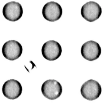
Another point is to assess whether there is a light center and a dark edge in the image of the formed joint. This is a direct result of the density of the formed joint, the weight of the layout and the construction of the pads. If there is one, then we have a great chance that the final product will “live”. Reverse coloring, unfortunately, will usually mean a defect, although contact by “contact” and any operation of such an arrangement is still possible.
A keen eye, in the lower, middle point of the photo, will notice small anomalies that look like holes. This is an inherent part of the formed solder joint, occurring mainly in lead-free technology. Professionally they are called, solder gaps. IPC standards set their maximum size at 30% of the joint surface, with no loss in its quality. However, looking at this phenomenon through the prism of common sense, allowing larger gaps than 20% can contribute to future cracking due to the resulting stresses between the PCB and the circuit. The most common causes of damage, due to gaps in the solder, are vibration and frequent temperature changes. The resistance of such an “insecure” connection also increases, which is never good for the life of the module. In our company to maintain the highest quality of production, we make great efforts to ensure that this parameter does not exceed 15%. We achieve this by using the highest quality solder pastes, a properly refined screen printing process and profiling each new product on reflow ovens.
Micro transistor at high magnification. The visible graininess is the result of maximum magnification. Its actual size is 1.2 x 1.2 [mm]. Using an analogous grading method as in photo 2, we know that the correct connection was formed only on the pad located in the upper right corner. Such an arrangement will not work properly.
These are, of course, only some of the errors that can be located, but they are the ones that most often contribute to the non-functioning of the entire, assembled system.
For those who are most interested, in the form of checking the acquired knowledge, we add a photo with quite a few errors, on which we can look for “what went wrong” ourselves.